
The construction of a traditional current loop for the capture of pressure sensor signals has its pitfalls – especially when not only a signal must be transmitted to the PLC, but also a local indicator has to be integrated. Let’s have a look at the example of a pressure sensor with the output signal that is most commonly used in industry, 4 … 20 mA, and its connection to a PLC.
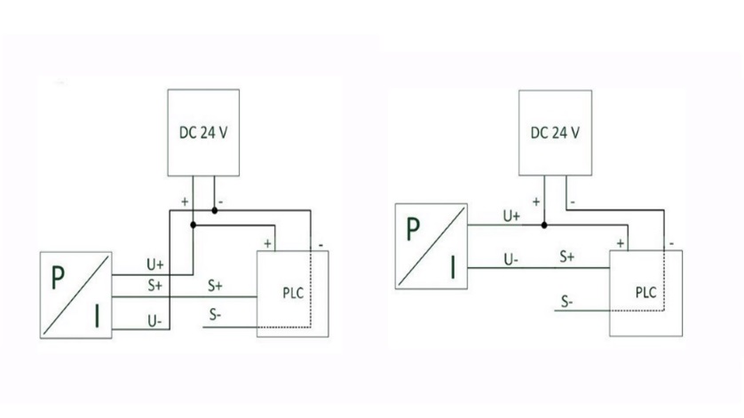
Again and again, in the design of current loops confusion arises, since in day-to-day implementation basic technical facts are no longer automatically known. Here’s an example: When connecting sensors to the PLC, a “single-wire design” is frequently used. With this, a 3-wire sensor is connected to an external power supply unit and then connected to the PLC with an additional wire. However, this system only works on condition that both parts are connected to the same power supply – an important detail which is often forgotten. This becomes evident if a 2-wire sensor should be connected with a 4 … 20 mA output: Three wires are available, but the pressure sensor only offers two connections. Here, the clear assignment and cabling of current and signal wiring is not always simple (see also the main picture: “Single-wire design”: Correct connection of 3- and 2-wire pressure sensors).
Additional Integration of a local indicator into the PLC
Integration of pressure sensors into the PLC
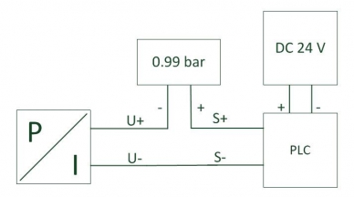
The complexity increases when a local digital indicator for the measured value is to be integrated into the circuit, in the given example, a 2-wire instrument. As is generally understood, a pressure sensor converts the measured pressure into a current value, which is normally transmitted with 0 bar as 4 mA and the maximum of the measuring range as 20 mA. The intermediate values are proportional. In order that the measured value can be read locally, the digital indicator required for this – in the simplest case – is integrated directly into the current loop and also powered via this.
Since the digital indicator and the pressure sensor are connected in the circuit in series, it must be checked that the PLC can provide enough energy. Depending on the manufacturer, the information is hidden behind a variety of terms found in the data sheets for the individual components. Users must strictly check these functional data for compatibility so that sensor, indicator and automatic signal processing within the PLC actually fulfil their function. Due to the series connection of the circuit, and the 4 … 20 mA signal selected in the example, the voltage of the PLC at 20 mA must equal the sum of the two minimum operating voltages of sensor and indicator. Only then can the signal also utilise the full range of 4 … 20 mA. A PLC voltage that is too low would first be seen on a rise in pressure: Even at the highest pressure, 20 mA would not be reached, and so a system pressure of 100 bar, for example, would be shown as a maximum of 85 bar.
Some manufacturers have recognised this complexity and therefore additionally specify the “load” (i.e. the resistance) that their instrument represents. The current loop works properly when the sum of the resistances of the sensor and indicator is smaller than the maximum load at the PLC input Card.
Note
Further information on electronic pressure sensors and electronic pressure switches can be found on the WIKA website. Should you need any help with choosing a suitable switching solution for your pressure, temperature or level measurement requirement, your contact person will gladly be of assistance.