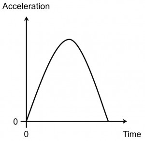
In many pressure sensor applications, short-duration, high, impact loading occurs – this is referred to as shock. Shock resistance defines up to what level of acceleration the instrument can withstand the shock loading without being damaged in any way.
The loading that acts during the shock is specified as a multiple of the acceleration due to gravity [g = 9.81 m/s²]. In addition, the duration of the loading is noted. A loading of 3 g will occur, for example, in a parachute landing, while 25 g will act on a car driver who crashes into a solid wall at 80 km/h with a 1 m crumple zone for “braking”. 100 g will occur when an object falls from a height of one metre, if it hits the ground and is decelerated within a millimetre.
The harder the ground is, the higher the loading. Commercially available pressure transmitters offer a shock resistance of approx. 100 to 500 g over up to 10 ms.

Half-sine shock
Shock tests are performed in accordance with the IEC 60068-27 standard. You effectively distinguish between 3 different types of shock. The half-sine shock, the sawtooth shock and the trapezoidal shock. At this point we will restrict ourselves to the half-sine shock because this is the most widely-used.
The semi-sinusoidal shock replicates the shock which occurs with the initiation and braking of oscillating components. The figure illustrates the acceleration curve. Manufacturers of pressure transmitters take a variety of measures to ensure the required shock resistance for any particular application. Some of these measures are described in more detail below.
- The cases are designed to be as squat as possible in order to prevent high lever loading. In addition, stainless steel cases are generally more robust than plastic cases and can withstand mechanical loading far better. One disadvantage is that the pressure transmitter is heavier and thus the loading on the connection threads increases.
- On the inside, the electronic components are protected by potting. This elastic encapsulation provides a counteraction against those forces exerted by the shock on the circuit boards and also prevents them impacting against the case itself.
- For the electrical connections, it is safer to use crimp contacts instead of soldered joints. The biggest disadvantage of soldered joints is that the soldered cable may break at the transition between the tinned part of the cable wires and the flexible part. It is there that the greatest loading occurs with high vibrations and shock. With crimping, the load is distributed better and the cable won’t break. However, a crimp is more expensive and technically more complex to implement.


Very nice information.