
Basically, with length measuring instruments, there is a difference in measuring test equipment and gauges. Among gauges, tapered thread gauges can be seen as a specialcase. A tapered thread gauge is a three-stage ring. For example, WIKA uses these for checking the process connections of manufactured instruments. By contrast, this test equipment will also be used to check the delivery.
The basics for tapered thread gauges is that the test item must reach the first stage (otherwise the thread is too large) and must not overstep the last stage. The middle stage represents the optimum measure in this context. In the past, calibration of the reference gauges with a master mandrel merely stated whether the thread would fit or not. Information about the relationships of the pitch diameter could not be derived and therefore no conclusion on the development of wear was possible. In ISO 9001, for example, pitch diameters are also mentioned. A calibration associated with this means that the actual dimensions of the pitch diameter must be determined. For a tapered thread, this requires a machine-aided method.
Carrying out a calibration at WIKA
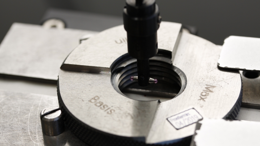
In order to be able to calibrate both one’s own and tapered thread gauges from customers in WIKA’s manufacturer-independent calibration laboratory, the Abbe comparator, developed by Carl Zeiss Jena, is used. According to the Abbe principle for the construction of length measuring instruments, the measuring scale and the test object mist lie in alignment to achieve the highest possible accuracy. Based on the Heidenhain scale, the reference is determined by means of an incremental method and the measuring lines are recorded by a sensor. The zero point can be set anywhere on the scale.
In conjunction with this measuring system, an inductive measuring probe with two ruby balls is used. Their diameter is based on the thread to be measured. Under the measuring probe is the so-called sine table, which accommodates the thread gauges to be tested and on which the test item is fixed. At this time, a 30 mm parallel gauge block maintains its surface exactly level. In the second step, the sine table is lowered by half a cone step, that is: set to a 26.7 mm final dimension, and the measuring probe is inserted into the thread of the now flat cone side. Thereafter, the sine table is raised to a 31.123 mm final dimension and the thread’s opposite location is measured. Subsequently, the reference gauge is rotated through 180° to measure the other cone width. The four measuring points result in the actual dimensions of the pitch diameter. Based on the findings on the current cone conditions, the further wear is derived. Thus, thread gauges can be replaced in good time and imprecise measurements can be avoided.
Note
If you have any questions, please do not hesitate to contact our serviceteam on workdays from 7 am to 4 pm (Fri. until 3 pm) by telephone on +49 9372 132-5049. For more information about our calibration & service centre, visit the WIKA website.
See also our article
Accurate down to the last µ – calibration of length measuring instruments