
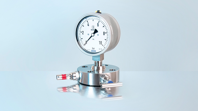
Monoflanges combine the function of up to three valves in a particularly compact body, thanks to a precise network of internal passages and valve chambers. But what really happens inside a monoflange valve, once installed?
In a chemical process a high response speed is required for most control applications. One of the variables that affect the response time is the volume and the distance between process and instruments. If the medium to be measured is gas, and the process tends to fluctuate strongly at times or if the control is critical, mounting the instrument near the process is the solution.
Vibrations are also critical, for example, in case that impulse lines are connected to a vessel. The longer the hook-up, the wider is the amplitude of the vibration causing possible failures of the nozzle. A monoflange includes one, two or three needle valves inside a compact, flange-shaped body, allowing a significant reduction in volume, dimensions, weight and potential leakage points.
Monoflange is the solution
Depending on the requirements of the plant it is installed in, the monoflange can incorporate one, two or three valves. In a monoflange with two valves (block & bleed), one valve (with a blue cap) isolates the process and the other (with a red cap) regulates the venting of the medium trapped inside the instrument. This is mostly used in applications that are relatively uncritical (e.g. low pressure) or where a first shut-off valve is provided just before the monoflange.
The safest configuration, and the one we advise for aggressive media or critical operating conditions, is the three-valve monoflange or the so-called double block & bleed (DBB), which features two shut-off valves in series and one valve for venting.
Monoflange functionality
The monoflange bodies are drilled internally with holes which connect the annular valve chambers.
The following picture illustrates the process within a DBB monoflange:
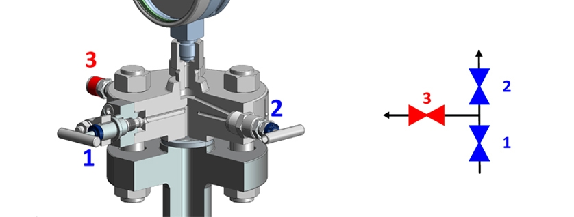
- The flow enters the monoflange from the pipeline and stops below the first shut-off valve [1];
- When the first shut-off valve [1] opens, the flow proceeds towards the second shut-off valve [2] ; when the valve [2] is open, the instrument is thus connected to the process line;
- When the first shut-off valve [1] is closed, the medium trapped between valve and instrument can be discharged via the vent valve [3] through the vent outlet. The two shut-off valves [1, 2] are in an angled position, which allows the flow to pass through them.
The two shut-off valves allow a better isolation from the process: In case the first shut-off valve does not isolate the medium properly, the second one will act as a safety means against accidental leaks. In some cases, customer specifications do not allow the medium to be in touch with the instrument when it is not measuring. For this reason the medium shall be discharged using the vent line. In other cases – due to the vent line – instruments can be easily calibrated without dismounting them from the line.
Note
Further information on our valves can be found on the WIKA website or in the video What is a monoflange? If you have any questions, your contact will gladly help you.