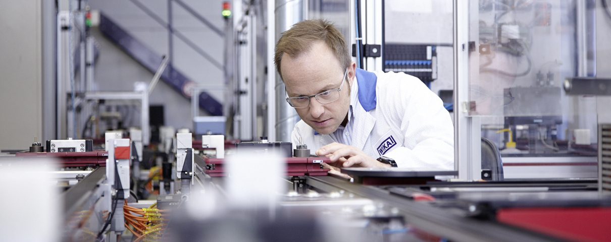
Mechanical pressure switches are usually supplied with a factory-set switch point. Nevertheless, some users want to make this configuration themselves, as, for example, the pressure conditions in the application can change. In the case of pressure switches with a measuring element in a bellows, diaphragm or piston design, the manual setting of the switch point, reset point or hysteresis (depending on the model) requires a certain amount of effort. But it’s not witchcraft. This article explains, step by step, how to do it.
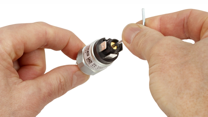
Users need the following equipment: a pressure source (e.g. a dead-weight tester), a control pressure gauge, a continuity tester or a control lamp as well as a tool for the adjustment screw (by the way, WIKA supplies the appropriate Allen key with its instruments; a conventional screwdriver is sufficient for setting the hysteresis).
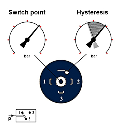
Setting plan view for the model PSM02 mechanical pressure switch from WIKA. The pin assignment 1 and 3 (small picture) corresponds to the switching function “normally closed”, the assignment 2 and 3 would be for “normally open”.
Setting of the switch point
- First, screw the pressure switch into the pressure source connection and connect its electrical connections to the continuity tester or control lamp.
- Turn the adjustment screw for the switch point in completely. This sets the switch point to the highest possible value.
- Now apply the desired switching pressure to the pressure switch until the control pressure gauge indicates the value.
- After that, turn the adjustment screw out until the instrument switches and the continuity tester or the control lamp reacts.
- Then lower the pressure until the pressure switch switches back and then increase it again to check the switch point. If necessary, the switch point must be corrected by turning the adjustment screw. Repeat the procedure until the desired switch point is reached.
Setting of the reset point
In some applications, the reset point is set instead of the switch point, e.g. for minimum pressure monitoring. Here the procedure is similar to the switch point, but without turning in the adjustment screw.
- Increase the pressure until the instrument switches.
- Then lower the pressure until the instrument switches back and adjust the position of the adjustment screw accordingly. The rule of thumb here is:
Set point < Actual value: Turn the screw out
Set point > Actual value: Turn the screw in
Setting of the hysteresis (not with all models)
To do this, first set the switch point and then check the reset point (see above). Depending on the reset point, the hysteresis screw is turned in or out. The switch point must then be checked, as changes to the hysteresis screw also affect the switch point.
Note
An overview of the various mechanical pressure switches as well as further technical information can be found on the WIKA website. If you have any questions, your contact will gladly help you.
Also read our articles
Mechanical vs. electronic pressure switches: Functionality
Mechanical vs electronic pressure switches: Application areas
Pressure switches in booster pumps
SIL pressure switch: Safety in tyre manufacturing