
In the specification of the switch points of a float switch, misunderstandings always lead to unsuitable product designs. How one correctly specifies the switch point of a float switch will be explained here.
The basic prerequisite for the correct specification and the manufacturing to requirements of a float switch is that both the customer and manufacturer have a uniform reference condition. Float switches are specified with the following parameters:
• Installation from above (process connection above float body)
• Dimensioning from the sealing edge downwards
• Empty tank – float is in the rest position on the limiting element
• Level rising
• Density of the medium: 1.00 g/cm³
The contact functions of a float switch
Three contact types / switching functions can now be defined for the specification of a float switch:
• Normally open / n.o.
– the contact closes as the filling level increases
– the contact opens when the filling level drops again
• Normally closed / n.c.
– the contact opens as the filling level increases
– the contact closes when the filling level drops again
• Change-over contact / SPDT
– the 3-wire contact provides two output circuits, which can be connected as required
– one output closes as the filling level increases / opens when the filling level drops again
– one output opens as the filling level increases / closes when the filling level drops again
The specification of the switch point
The correct specification of the switch point of a float switch with a switch point, as an example:
• Switch point position 150 mm (from the sealing edge to the desired switching level)
• Switching function normally open / n.o.
• Guide tube length 200 mm (from the sealing edge to the end of the tube)
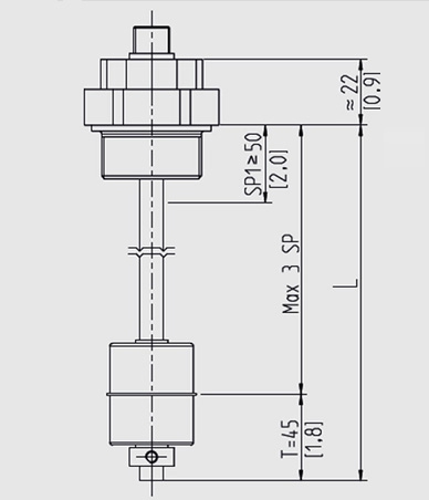
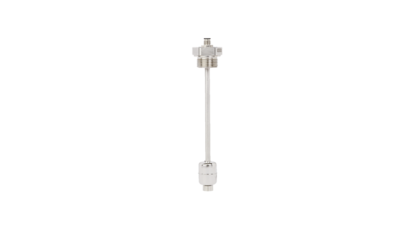
Float switch (drawing)
The guide tube length “L” must always be greater than the distance between the switch points from the process connection in order to allow the float body to assume a rest position, in which the switching output is not yet switched (cf. drawing). From the rest position, the float rises with increasing level and switches the desired function (e.g. normally open) at the defined level (switch point position).
The guide tube length is defined by the lowest switch point + dead band “T”. Depending on the size of the selected float body, the dead band is generally between 25 and 50 mm and is also defined in the manufacturer’s data sheet.
Expert tip: Density dependency and hysteresis of the switch point
The float, as a suspended hollow body, is influenced by the density of the medium. For very low-density media (e.g. light oils), the float will immerse deeper in the medium than in the reference medium of water with a density of 1 g/cm³. This deeper immersion of the float will result in a small deviation of the switch point position by a few millimetres.
Last but not least, the hysteresis of a reed contact causes the reset point of a float switch to be a few millimetres below the switch point.
Note
As a leading provider of float-based, measurement technology solutions, WIKA has a wide range of variants to meet all your application-specific requirements. Our range of float switches can be found on the WIKA website. Your contact person will be pleased to advise you on the selection of the appropriate product solution and specification of the switch points.