
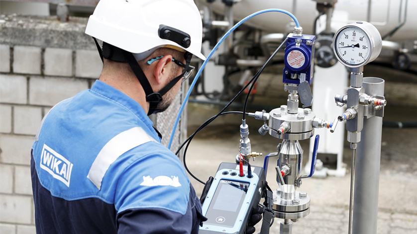
In-situ calibration of measuring instruments is carried out in numerous industrial processes. The advantages are obvious: The instruments remain installed, so the process does not have to be opened. In this way, plant operators reduce the time and costs involved in testing. At the same time, they rule out potential errors when reinstalling the instruments following their calibration in the laboratory. A prerequisite for in-situ calibration is usually the setting up of the measuring location with appropriate instrumentation valves, as shown below, using an example of pressure switch measuring locations in an incineration plant for liquid waste.
The operator of the plant is a company that specialises in the disposal of contaminated residues from the chemical industry. In its incineration plant for liquid waste, 46 pressure switches perform central monitoring tasks. This primarily involves maintaining the energy supply for the incineration process. If the pressure required for this falls below the defined limit value, the measuring instruments trigger a process stop. This is because, with an insufficient supply of natural gas, air and steam, for example, the plant cannot incinerate the substances fed into it properly. In such a case, the operator must therefore immediately determine the cause of the insufficient pressure. A blocked pipe or a technical defect would be typical examples.
46 pressure switches require a considerable amount of testing
The pressure switches are calibrated once a year during the regular system shutdown. Previously, the company had the instruments disassembled for this purpose. This meant that they were first electrically disconnected and then disassembled. The pressure switches were then sent to the company’s own test laboratory and, after successful calibration and any necessary adjustments, returned to the plant for installation. Given the number of 46 pressure switches, the testing process required a considerable amount of time and effort, which was further exacerbated by the confined installation environment.
The company was looking for an alternative and, in collaboration with WIKA, implemented the possibility of in-situ calibration. It is based on two instrumentation valve models from WIKA, to which the pressure switches were screwed and connected to the process. Depending on the installation situation, these are the compact model IVM monoflange and the model IV2 valve block, both in block-and-bleed version. As the measuring points in question are safety-relevant, the company opted for valve variants with a removable handle: they prevent unintentional adjustment of the valves and thus impairment or even decommissioning of the attached measuring device.
In-situ calibration increases system availability
For in-situ calibration, the operator first closes the block valve. This isolates the pressure supply to the switches from the process. This is followed by venting via the bleed port. This is also the interface for the calibrator and the pump for generating the test pressure. The switch point is approached three times with the mobile test instrument and adjusted if necessary. Calibration is therefore completed in a much shorter time, which increases plant availability. At the same time, the entire loop from the pressure switch to the control room is tested in one go. This also provides the operator with information on the deviation of the entire active chain in the electrical loop, including the display, alarm or switching action.
However, a measuring location for in-situ calibration offers yet another advantage: If a fault is suspected between the regular calibration intervals, the switching functions and limit values of individual pressure switches can also be checked while the process is running.
Valves fulfil high demands on safety and service life
The instrumentation valves from WIKA, selected for in-situ calibration, fulfil the customer’s requirements for safety and service life of process components. The upper bodies of models IV2 and IVM have a blow-out proof valve spindle and a non-rotating spindle tip with metal seat for low-wear operation. A low torque ensures smooth and precise valve adjustment, even at high pressures. Both valves are also available in a version to prevent fugitive emissions, in accordance with ISO 15848-1 and TA-Luft (VDI 2440).
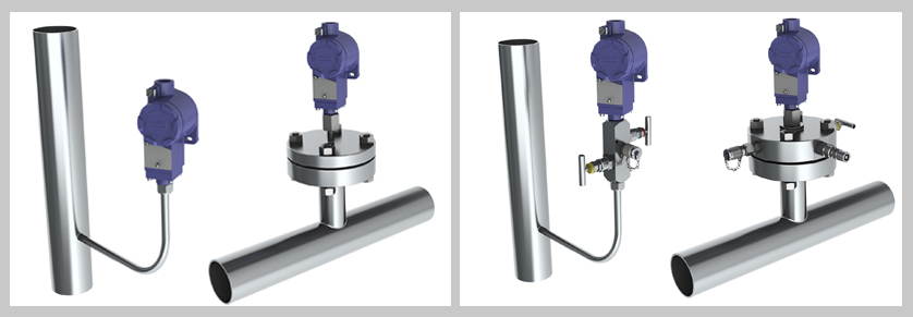
Before – after: Pressure switch measuring locations in conventional design (left illustration) and with WIKA instrumentation valves for in-situ calibration (right illustration), in this case with model IV2 valve block and model IVM mono flange (right).
Note
On the WIKA website you will find further information on the IVM and IV2 instrumentation valves as well as an overview of other valves and protective devices. There, you can also find out about WIKA’s measurement solutions for the chemical industry in general and specifically for the prevention of fugitive emissions. For the on-site calibration of pressure measuring instruments, we also feature the CPH7000 portable process calibrator, the CPP30 hand test pump and the CPG1500 precision digital pressure gauge on the website.
In addition, WIKA offers a customer-specific assembly with measuring instrument for all valves. Such “instrument hook-ups” are delivered ready for operation and leak tested.
If you have any questions, your contact will gladly help you.
Also read our posts
Avoiding fugitive emissions through prevention
Play it safe with double block & bleed
How does a monoflange work?
Combination of pressure measuring instrument with accessories: Instrument hook-up instead of own assembly