
A float-based level sensor with a reed chain is a widely used and comparatively economical solution for continuous level measurement in vessels. Users can define its measuring range flexibly within a given range. This article describes what needs to be taken into account.
With a reed-chain level sensor, the guide tube contains a defined number of reed contacts, depending on the measuring range. These are combined to form a measuring chain. The contacts react to the magnetic field of the float, which moves within the guide tube in line with the liquid level.
Accuracy depends on the distance between the contacts
The accuracy of this energy-free level monitoring depends, in turn, on the distance between the individual contacts: the smaller it is, the more accurate the measurement. Each level sensor in WIKA’s RLT series, for example, enables measuring ranges with contact distances between 3 and 24 mm. However, a reed chain cannot be stretched along the entire length of the guide tube. This is because there are ‘dead bands’ at both ends of the tube, i.e. sections that the float does not detect due to design constraints (see graphic).
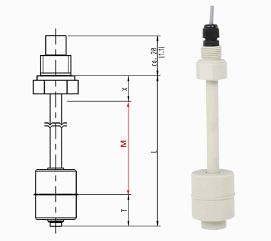
The graph shows how the maximum possible measuring range (M) with an air-handling series level sensor is defined: Guide tube length (L) minus dead band (T) and 100 % mark (X).
Maximum measuring range is not a must
The measuring range of a level sensor therefore lies between the two dead bands specified in the data sheet. Within this range, it can be freely defined. However, it is by no means necessary to utilise the maximum possible measuring range in all applications. The exact adaptation of the number of contacts to the measuring task also has an economic advantage: The reed chain is one of the most expensive components in a level sensor.
Example − Dry run monitoring
For dry run monitoring in an oil tank of a compressor, for example, only the lower part of the guide tube is needed for the measurement. In this case, the upper measuring point of the application (100 % mark) is set correspondingly low. It marks the distance to the sealing face of the process connection. The measuring range is thus defined by the following equation:
Measuring range length M = guide tube length L – dead band T – 100 % mark X
Consequently, the measuring range for detecting a maximum level is determined starting from the sealing face. In this case, the guide tube can be adapted to the length of the measuring range.
Note
Further information on the RLT series level sensors can be found on the WIKA website. If you have any questions, your contact will gladly help you.
Also read our articles
Level sensors – the agony of choice
What do dead bands mean with a float switch?
You can also find out more about float-based level measurement using a reed chain in the following video: