

Float switches with reed contacts enable both reliable and economical level measurement. Accordingly, they are used in a wide variety of applications. As with all level sensors using the float principle, users must pay attention to the dead bands when configuring the float switches. What is this design-related variable all about?
A float switch, essentially, consists of a hollow body (float), a guide tube, an electrical output and a process connection. The float is designed for buoyancy in the respective liquid. Thus, it always moves on the guide tube in line with the level. In order to detect its level, float switches, such as the instruments of the RLS series from WIKA, work with reed contacts.
Float switches operate potential-free
The reed contacts are mounted in the guide tube. They are closed or opened by a ring magnet in the float. The switching is carried out potential-free.
The float switches of the RLS series can be fitted with up to four switch points. Their positions can be distributed along the guide tube as required. However, the user must first ensure that the magnet of the float actually “passes over” the reed contact. But this is not possible over the entire guide tube length. This limitation can be explained as follows:
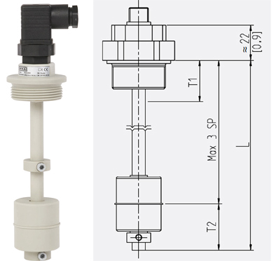
In the case of a float switch with reed contacts, such as the model RLS-2000 shown here, the dead bands T1 and T2 must be taken into account when determining the switch points on the guide tube.
- Measuring the switching height
The switching height of a float switch is measured from the sealing face of the process connection. However, due to the physical design, the float and magnet cannot reach this point of the measuring arrangement. Therefore, the first switch contact must always have a minimum distance to the sealing face. This distance is called the dead band (T1 in the adjacent figure). Its dimension depends on the height of the float and also the respective process connection.
- Retaining ring at the end of the guide tube
Another such dead band must also be taken into account at the end of the guide tube (T2 in the figure). There, a retaining ring prevents the float from slipping off, which is why the magnet does not reach the end of the tube. It follows that the minimum length for a guide tube must be calculated from the position of the lowest switch point plus T2.
Dimensions of the dead band in the data sheet
In the case of the RLS float switches, the dimensions of the dead bands are listed in the respective data sheet. For example, for the model RLS-2000, they range between 20 and 60 mm (T1) and between 30 and 55 mm (T2).
Note
Further information on the instruments of the RLS series can be found on the WIKA website. If you have any questions, your contact will gladly help you.
See also our post
Float switch: What is it and how does it actually work?
How does one specify the switch point of a float switch?
You can also find out more about level monitoring with float switches in the following video: