

Temperature sensors are essential measuring instruments for ensuring the safety and efficiency of countless industrial processes. While RTDs and thermocouples both provide accuracy and reliability, each has pros and cons that make them better suited for particular applications.

RTD
Resistance thermometers (RTDs) and thermocouples are the two most common types of electronic temperature sensors used in industrial processes. The choice of which one to use depends on a variety of factors. First let’s take a look at what RTDs and thermocouples are, and how they differ from one another.
In some applications, it doesn’t matter very much whether you use a resistance thermometer or a thermocouple. Other times, one type is definitely better than the other. In general, thermocouples are better for high-temperature and high-vibration processes, applications that require fast response times, and those with limited space. RTDs offer better accuracy, repeatability, and stability.
RTD vs Thermocouple: When to Use Each Temperature Sensor
In some applications, it doesn’t matter whether you use a resistance thermometer or a thermocouple. Other times, one type is definitively better than the other. In general, thermocouples are better for high-temperature and high-vibration processes, applications that require fast response times, and those with limited space. RTDs offer better accuracy, repeatability, and stability.
Before diving into how each sensor works, here’s a side-by-side look at how RTDs and thermocouples compare across factors that matter most for sensor selection:
| Factor | RTD | Thermocouple |
|---|---|---|
| Sensing principle | Contains a metal element, most often platinum, whose electrical resistance shifts predictably as temperature changes. The instrument reads that resistance and converts it to a temperature value. | Built from two different metal wires welded together at one end. The junction produces a small voltage as temperature changes (the Seebeck effect), driven by the temperature gap between that junction and a reference point. |
| Output type | Sends a resistance signal (ohms) back to the instrument. Wired in 2-wire, 3-wire, or 4-wire circuits, with lead wire resistance affecting the reading depending on which configuration is used. | Sends a very small voltage signal (millivolts). The instrument needs cold junction compensation and matched signal conditioning to read it correctly. |
| Temperature-to-output relation | Resistance climbs at a steady, predictable rate as temperature rises, producing an almost straight-line relationship. That predictability makes the signal easier to convert into an accurate reading. | Voltage output follows a curved, uneven path as temperature rises rather than a straight line. Each thermocouple type is fully mapped and standardized, so instrumentation can still translate the curve into an accurate reading. |
| Standardization | Governed by published resistance curves and accuracy classes under IEC 60751, most commonly seen in platinum Pt100 and Pt1000 sensors. | Grouped into recognized letter types (J, K, T, E, N, R, S, B), each with its own published voltage-to-temperature curve. |
| Operating temperature range | −321°F to 1,112°F (−196°C to 600°C) | −328°F to 4,200°F (−200°C to 2,320°C), depending on type |
| Accuracy | Generally the more accurate option. Actual accuracy depends on the sensor’s IEC 60751 tolerance class, temperature, wiring configuration and measurement instrument. Three- and four-wire circuits reduce errors caused by lead-wire resistance. | Typically less accurate than a comparable RTD in a standard build. Using calibrated units or higher-grade wire narrows that gap. |
| Long-term stability / drift | Generally offers better long-term stability and lower drift than a comparable thermocouple, although operating conditions and installation can still affect calibration. | More likely to drift as the metals age or react chemically over time, particularly when run at higher temperatures. |
| Response time | Generally slower than a comparable thermocouple because the sensing element and protective construction typically add thermal mass. Thin-film and small-diameter designs can improve response. | Generally faster, particularly with exposed or grounded junctions. Actual response time for either sensor depends on probe construction, diameter, thermowell design, process medium and flow conditions. |
| Vibration / installation environment | More sensitive to physical shock and vibration. Installation is straightforward, since no separate extension wire is needed. | Holds up better in environments with heavy vibration or high pressure, thanks to a more rugged build. |
| Typical cost | Runs more expensive, largely because of the platinum used in the sensing element. | Costs less for a similar probe style and temperature rating. |
| Best-fit use cases | A strong fit where accuracy, repeatability, and stability matter most at moderate temperatures: pharmaceutical, food processing, HVAC, and laboratory calibration work. | A strong fit for high-temperature processes, rough industrial settings, fast-changing temperatures, and budget-conscious projects: furnaces, automotive exhaust, and cryogenic work. (Certain thermocouple types, particularly T and E, are suitable for cryogenic measurement.) |
Ultimately, when choosing a temperature sensor, you need to consider the application’s
- Temperature range
- Pressure range
- Humidity
- Shock and vibration
- Media (solid, liquid, or gaseous; corrosive; hazardous)
- Flow rate
What is an RTD, and how does it work?
RTD stands for resistance temperature detector. This instrument is also called a resistance thermometer and, redundantly, an RTD probe or RTD sensor.
Within an RTD is a sensing element (resistor) that uses the change in electrical resistance of metal to determine the temperature. The most common metal in RTDs is platinum (Pt), as it is very chemically inert and has an almost linear temperature vs. resistance relationship. Platinum RTDs are often referred to as Pt100 sensors or Pt1000 sensors; the number refers to platinum’s nominal resistance (ohm Ω) at 0°C. Other metals used in RTDs are copper, nickel, and tungsten, but WIKA’s RTDs are made of platinum primarily because this metal has excellent stability, resists contamination, and its electrical resistance does not degrade over time.
Regardless of the metal used, its electrical resistance at specific temperatures is a known constant. As the temperature changes, so does the metal wire’s resistance. So, by comparing the known resistance to the measured resistance, one can calculate the temperature.
Types of RTDs
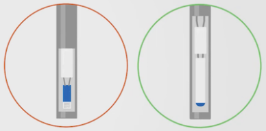
Thin-film (left) and wire-wound resistors
- Thin-film resistors are made up of a very fine layer of platinum deposited on ceramic and sealed by glass.
- Wire-wound resistors consist of a wire wrapped around and embedded inside a glass or ceramic casing.
RTDs also come with different numbers of wires in the cable.
2-Wire, 3-Wire, and 4-Wire RTDs: Which Configuration Do You Need?
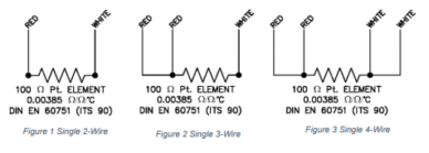
RTDs are available in three wiring configurations — 2-wire, 3-wire, and 4-wire. The difference comes down to how lead wire resistance is handled, which directly affects measurement accuracy. Choosing the right configuration is a tradeoff between cost and precision. Every wiring style shown below; 2-wire, 3-wire, and 4-wire, uses the identical 100 Ω platinum element (DIN EN 60751, ITS-90). The difference is how the lead wires are arranged, which determines how effectively lead-wire resistance is compensated. More wires generally mean more accuracy, since the extra leads let the measuring circuit cancel out resistance introduced by the wire itself.
2-Wire RTD
The simplest and least expensive configuration. The two lead wires connect the RTD to the measuring instrument, but their resistance is added to the RTD’s reading, introducing a measurement error. Best suited for short lead lengths or applications where high accuracy is not critical.
3-Wire RTD
The most common industrial configuration. A third wire allows the measuring instrument to calculate and subtract lead wire resistance, significantly improving accuracy over a 2-wire setup. For compensation to work correctly, all three wires must have the same resistance — meaning matched wire material, gauge, and length. This configuration covers the vast majority of industrial process applications and is the standard choice where ±0.3–0.5°C accuracy is acceptable.
4-Wire RTD
The most accurate configuration, used when measurement precision is critical. Two wires carry excitation current through the RTD; the other two measure voltage drop across the sensing element only, completely eliminating lead wire resistance from the reading. This true Kelvin measurement method means accuracy is not affected by wire length, gauge, or material mismatches. The 4-wire configuration is required for Class AA accuracy per IEC 60751 (the sensor element must also be Class AA rated) and is the standard for laboratory calibration and high-precision process applications.
Which Wiring Configuration Should You Choose?
| Configuration | Lead-Wire Compensation | Cost | Best For |
|---|---|---|---|
| 2-Wire | None; lead resistance is included in the measurement | Lowest | Short cable runs and non-critical measurements |
| 3-Wire | Good; compensates when lead resistances are closely matched | Moderate | Most industrial process applications |
| 4-Wire | Best; compensates for resistance in the individual leads | Highest | Laboratory calibration, high-precision measurement and long cable runs |
The Pros and Cons of RTDs
Resistance thermometers are popular for many reasons:
- High accuracy, up to class AA (4-wire RTD)
- High repeatability
- Wide compatibility with instruments and processes due to their widespread use
- Excellent long-term stability
- Easy installation, as no extension wires are required
- Ease of calibration
- Suitable for temperatures between −321°F (−196°C) to 1,112°F (600°C).
On the other hand, RTDs cannot withstand extremely high temperatures, such as those found in chemical, petrochemical, and refinery applications. Pt100 and Pt1000 sensors can be expensive, due to the high cost of platinum. There’s also the possibility of self-heating errors, and compared to thermocouples, RTDs have a slower response time and are more susceptible to extreme shock and vibration.
These recommendations are starting points rather than fixed rules. Final sensor selection should account for the exact temperature range, required accuracy, response time, vibration, process media, mounting arrangement, and any thermowell used.

Thermocouple with connection cable
What is a thermocouple, and how does it work?
Thermocouples are temperature sensors with a pair of dissimilar wires, each with a different electrical property at different temperatures. The working principle of thermocouples is that thermal energy is converted to electrical energy. At one end of the thermocouple, the two wires are welded or otherwise connected; this is the measuring point. When the temperature changes at this point, so does the electron density of each metal. The difference in temperature between the two metals creates a thermoelectric voltage. Since the relationship between temperature and voltage is known, this measured voltage is used to determine the temperature reading.
Thermocouple Types: Full Reference Guide
Thermocouples are classified by letter type, each defined by a specific alloy combination, temperature range, and optimal application environment. Base metal types (J, K, T, E, N) use less expensive alloys and cover most industrial applications. Noble metal types (B, R, S) use platinum-rhodium alloys for high-temperature and precision applications.
Base Metal Thermocouples
| Type | Alloy Combination | Temperature Range | Common Applications | Key Characteristic |
|---|---|---|---|---|
| J | Iron / Constantan | −210°C to 760°C (−346°F to 1,400°F) | Boilers, furnaces, general industrial | One of the few types suitable for reducing atmospheres; iron leg susceptible to rust above 550°C in oxidizing environments |
| K | Chromel / Alumel | −270°C to 1,260°C (−454°F to 2,300°F) | Most general industrial applications, nuclear, HVAC | Most widely used industrial thermocouple; wide range, low cost; susceptible to sulphur and “green rot” between 816–1,038°C |
| T | Copper / Constantan | −270°C to 370°C (−454°F to 700°F) | Cryogenics, laboratory, food processing | Excellent stability at low and cryogenic temperatures; suitable for oxidizing, reducing, and inert atmospheres; copper leg oxidizes quickly above 370°C |
| E | Chromel / Constantan | −270°C to 870°C (−454°F to 1,600°F) | Cryogenics, aviation, flow chambers | Highest thermoelectric output of all base metal types; non-magnetic; preferred over K and J at temperatures below 1,000°F |
| N | Nicrosil / Nisil | −270°C to 1,260°C (−454°F to 2,300°F) | High-temperature industrial processes where Type K instability is a concern | Superior oxidation and sulphur resistance vs. Type K; better repeatability between 300–500°C; preferred alternative to K at high temperatures |
Noble Metal Thermocouples
Noble metal thermocouples use platinum-rhodium alloys. They offer higher accuracy and stability at elevated temperatures but are significantly more expensive than base metal types and cannot be used in reducing atmospheres.
| Type | Alloy Combination | Temperature Range | Common Applications | Key Characteristic |
|---|---|---|---|---|
| R | Pt-13% Rh / Platinum | 0°C to 1,450°C (32°F to 2,642°F) | Steel industry, high-temperature furnaces, kilns | Slightly higher output and stability than Type S due to higher rhodium content; requires protective sheath to avoid contamination |
| S | Pt-10% Rh / Platinum | 0°C to 1,450°C (32°F to 2,642°F) | Medical industry, pharmaceutical, high-temperature lab and process | High accuracy and oxidation resistance; historically used as the international temperature standard; must be protected from metallic and non-metallic vapors |
| B | Pt-30% Rh / Pt-6% Rh | 800°C to 1,800°C (1,472°F to 3,272°F) | Powder metallurgy, sintering furnaces, vacuum furnaces, molten metal | Highest temperature range of all noble metal types; near-zero output below 50°C (no compensation wire required); both legs contain rhodium |

Thermocouples are made of two metals with different electron densities.
Most thermocouples are made of relatively inexpensive base metals, although some have metal pairings containing more expensive platinum, rhodium, rhenium, and tungsten.
The Pros and Cons of Thermocouples
Thermocouples are widely used in industrial temperature measurement because they are rugged, versatile, and capable of operating across a much broader temperature range than RTDs. Their primary advantages include:
- Wide temperature range: Depending on the thermocouple type and construction, thermocouples can measure extremely low temperatures as well as temperatures far beyond the usable range of an RTD.
- Fast response: Thermocouples can be manufactured with very small sensing junctions and generally have a faster response time than RTDs. Exposed and grounded junctions provide especially short thermal paths.
- Rugged construction: Their relatively simple sensing design makes thermocouples well suited to applications involving vibration, mechanical shock, high pressure, and other demanding operating conditions.
- Compact size: Thermocouples can be made with smaller probe diameters than most RTDs, making them useful where installation space is limited.
- Lower initial cost: Base-metal thermocouples are generally less expensive than comparable RTD assemblies, although noble-metal and specialty thermocouples can cost more.
- No excitation current required: A thermocouple generates its own millivolt signal from the temperature difference between its measuring and reference junctions.
Thermocouples also have limitations that must be considered:
- Lower accuracy: Standard industrial thermocouples are generally less accurate than comparable RTDs, particularly at low-to-moderate temperatures.
- Greater drift: Repeated thermal cycling and prolonged high-temperature exposure can change the thermoelectric properties of the conductors. Oxidation, contamination, mechanical strain, and other metallurgical changes can also cause measurement drift.
- Nonlinear output: The relationship between thermocouple voltage and temperature is nonlinear, so the measuring instrument must use the correct standardized conversion curve for the thermocouple type.
- Cold-junction compensation: Because a thermocouple measures the temperature difference between the measuring junction and reference junction, the instrument must compensate for the reference-junction temperature.
- Specialized wiring requirements: Extension or compensating cable must be compatible with the thermocouple type and connected with the correct polarity to avoid additional measurement errors.
- Potential electrical interference: The low-level millivolt signal can be affected by electrical noise and ground loops if the sensor, cable, and instrumentation are not properly selected and installed.
The complete sensor assembly also affects performance. A thermowell can protect the thermocouple from corrosive, abrasive, high-pressure, or fast-flowing process media, but its added mass generally increases response time. Junction design, probe diameter, sheath material, insertion depth, process medium, and flow conditions should all be considered when selecting a thermocouple assembly.
RTD or Thermocouple: Which Is Best for Your Application?
In general, use an RTD when you need high accuracy, repeatability, and long-term stability within the sensor’s rated range. Choose a thermocouple for extremely high temperatures, faster response times, or high-vibration environments. The following recommendations provide a starting point for common applications.
| Application or Condition | Temperature and Measurement Priority | Recommended Sensor | Why? |
|---|---|---|---|
| Food, beverage, pharmaceutical, and biotech | Low-to-moderate temperatures; repeatability and accuracy | RTD | Sanitary processes rely on long-term stability and precise temperature measurement. The complete assembly must also meet the application’s sanitary-design requirements. |
| HVAC, cold storage, and building automation | Low-to-moderate temperatures; stability and repeatability | RTD | RTDs are ideal for standard ambient ranges where stable environmental monitoring with minimal drift matters most. |
| Labs and high-accuracy process measurement | Controlled temperature range; high accuracy, repeatability, and stability | Platinum resistance thermometer (PRT) | When small temperature differences matter, a PRT provides accuracy, repeatability, and stability. Choose an industrial, precision, or reference-grade instrument based on the measurement uncertainty the application requires. |
| Bearings, motor windings, and pump housings | Low-to-moderate temperatures; vibration resistance with accuracy | Thin-film RTD | Compared to wire-wound, thin-film designs are compact and can better resist the constant vibration of motors, bearings, and other rotating equipment while maintaining accuracy. |
| High-temperature combustion monitoring, exhaust gas, and fast-cycling processes | Elevated or rapidly changing temperatures; fast response | Thermocouple | Fast thermal response is critical in these applications. Exposed or grounded-junction thermocouples can react much faster than RTDs to sudden temperature changes. |
| Kilns, furnaces, metals processing, and high-temperature refining | Temperatures beyond the usable range of an RTD | Thermocouple | These temperatures exceed the practical range of standard industrial RTDs. Select the thermocouple type based on the maximum temperature and process atmosphere. |
These recommendations are starting points rather than fixed rules. Final sensor selection should account for the exact temperature range, required accuracy, response time, vibration, process media, sensor and sheath construction, mounting arrangement, and any thermowell used.
Calibrating RTDs and Thermocouples
Temperature sensor accuracy can change with use. How quickly it changes, and how predictably, depends on the sensor type, operating conditions, and required measurement accuracy. Those factors should help determine the calibration schedule.
Why Calibration Matters
Platinum RTDs, including Pt100 and Pt1000, are generally more stable than thermocouples. Platinum is chemically inert and has a highly predictable resistance-to-temperature relationship, but the complete RTD assembly can still drift due to mechanical strain, vibration, thermal cycling, contamination, moisture, lead-wire resistance, or installation conditions. Calibration verifies whether the sensor remains within the required tolerance. Under IEC 60751, for example, a Class B RTD has a tolerance of ±(0.3 + 0.005 × |t|)°C.
Thermocouples are generally less stable than RTDs, though they have a faster response time and are better suited to high-temperature, high-pressure, and high-vibration environments. High temperatures, repeated thermal cycling, oxidation, contamination, grain growth, and mechanical strain can change the thermoelectric characteristics of their conductors. The resulting error depends on the thermocouple type and its exposure history, making drift difficult to predict from age or operating hours alone.
In Type K thermocouples, aging typically occurs between 600°F and 1,200°F and causes a slight increase in the indicated temperature. The normal maximum deviation is typically about 5–6°F. Above 1,200°F, drift can cause a significant decrease in the indicated temperature and may eventually result in thermocouple failure. Because thermocouple drift depends on the sensor’s exposure history and cannot be reliably predicted, errors of 10–20°F are common.
How Often Should You Calibrate an RTD or Thermocouple?
WIKA generally recommends a calibration check and recertification once every 12 months as a starting point. The appropriate interval ultimately depends on the application, applicable accuracy and quality requirements, and the instrument’s calibration history. Conditions that may justify a shorter interval include:
| Factor | Why It Shortens the Interval |
|---|---|
Operating conditions | Shock, vibration, and extreme thermal cycling can accelerate mechanical and electrical drift. |
Process criticality | Safety- or accuracy-critical measurements require a tighter margin for error and may need more frequent verification. |
Because thermocouples generally drift faster and less predictably than RTDs, heavy-duty thermocouple installations may require more frequent checks than RTDs used in comparable service.
Dry Well Calibrators
A dry well, also called a dry block calibrator, is commonly used for on-site RTD and thermocouple calibration. It consists of a portable, temperature-controlled metal block with interchangeable inserts sized for different probe diameters. The sensor is removed from the process, inserted into the block and checked at one or more test temperatures. For routine field verification, its reading can be compared with the calibrator’s indicated block temperature, within
the calibrator’s specified uncertainty. When lower measurement uncertainty is required, a calibrated external reference PRT can be inserted alongside the sensor under test so their readings can be compared at each stabilized temperature.
WIKA’s CTD9100 series combines a stable temperature source with precision Pt100 temperature measurement. The series offers an accuracy of ±0.20–0.50 K, depending on the model, and a 150 mm (5.91 in) insertion depth helps reduce heat-dissipation error. The portable, simple-to-use system is designed for routine on-site calibration of industrial temperature probes.
Learn about WIKA’s calibration services for temperature measuring instruments →